


Cat Single Life Cutting Edges
Cat Ground Engaging Tools (GET)
Cat Single Life Cutting Edges
Maintenance-Free Cutting Edge Options for Medium Wheel Loader Fleets
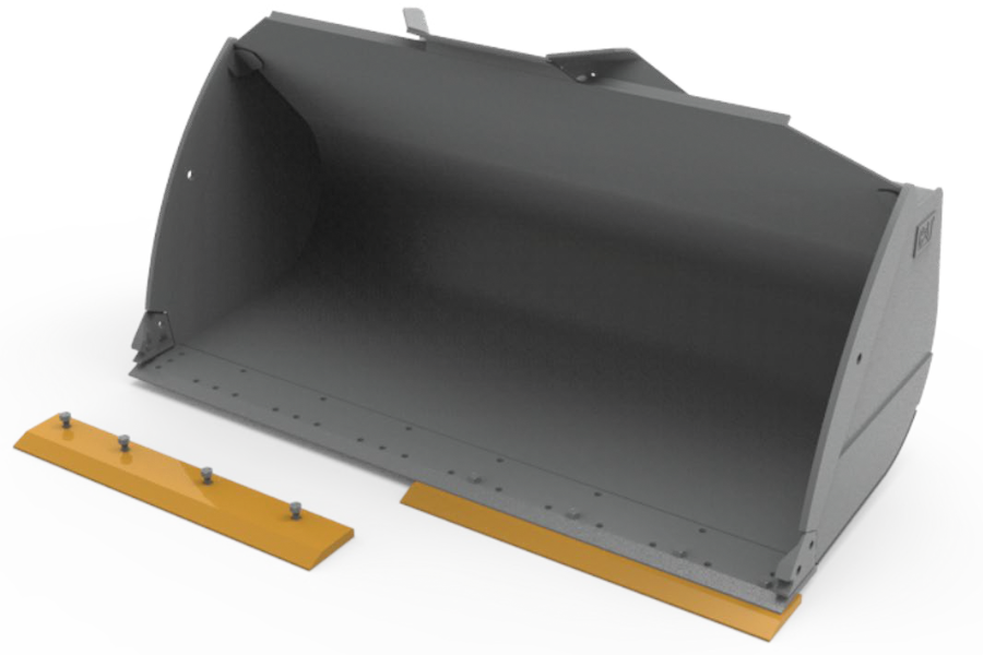
ENHANCED DURABILITY
- One-way edges made from throughhardened DH-2 steel can endure both high impact and abrasion
- Provides similar life to standard cutting edge option via increased thickness at a lower price point*
- Reduced throwaway material
- Backed by Cat Limited Warranty**
SIMPLIFIED MAINTENANCE
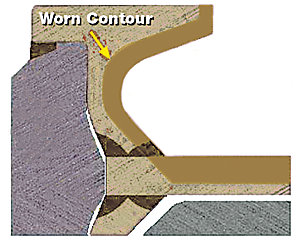
- Single bevel design eliminates the need to monitor wear for flipping edges
- No need for new hardware at mid-life (edge flip)
- 2 cutting edge pieces to fit bucket, no end bits required
ADDITIONAL ADAPTABILITY
- Offered for wheel loader models from 950 through 980
- Retrofittable to aftermarket buckets with the same hole pattern
- Bucket fit can be found in Cat Expert, linked to buckets and as alternate parts to existing cutting edges
* 950 through 980 Models. All Comparisons versus legacy Cat GET Cutting Edge Systems
**Terms and conditions apply
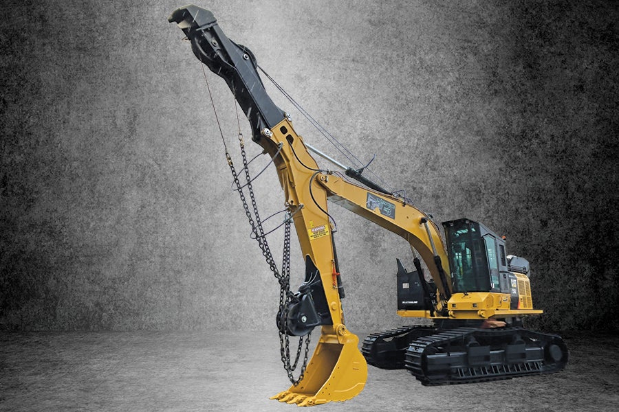
Tractionline
Peterson Cat is your source for sales, support, and service for Tractionline, Harvestline, and Hawkeye forestry products in Northern California, Oregon, and Southwest Washington.
Improved Pulling Power: 50,000 lbs Total Pull
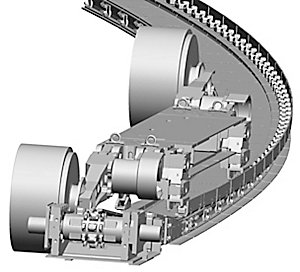
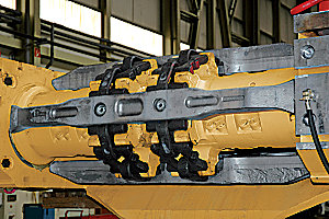
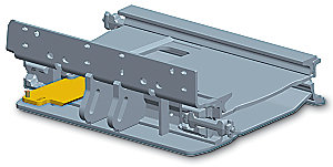
The Tractionline is a twin line traction winch assist system designed for steep slope harvesting and manufactured to meet stringent safety standards. The winches are wirelessly controlled by the machine that is being tethered.
Features
- Live constant tension (cables always under tension)
- (2) 1,700 ft 7/8 compact swag cables (230,000 lbs breaking strength)
- Excellent for tight road set-ups with the ability to tether at right angles from boom
- Adjustable tension on the fly from tether machine
- Dual Line system with 50,000 lbs total pull
- Separate tension settings for both inhaul and outhaul
- Add additional tether machines for approximately $2,500
Best In Class Live Constant Tension
Make tension adjustments in one ton increments to reduce loads on stumps when side washing. (Others use only high, medium, or low settings.) Tensions are separate for inhauling and outhauling.
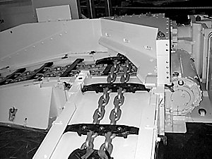
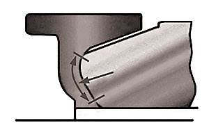
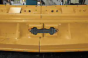
Reversed Bucket
- Unparalleled holding force. Others rely on weight of winch base alone.
- Allows work at right angles from boom at full tension.
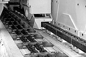
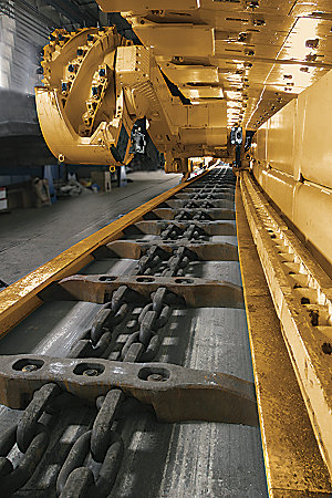
Lower Swiveling Sheave
(IN CONJUNCTION WITH BUCKET DIG IN)
- Chains can pass through sheaves under full tension.
- Tether machine can drive right up to the lower sheave under tension.
- Reduces winch base moves. Operator can cut more trees from one set-up.
- Reduces sidewashing, which increases line pull and more pulling power to move around the slope.
- Allows Tether machine to leave and return to road under tension.
- Only requires part of the road to keep road open for other traffic.
Transit Mode
Maintains a small amount of tension on the lines so one operator can move the winch base without worrying about slack in the lines.
- Allows the boom to be lifted and swing the lines over obstacles when moving.
- Lines do not have to be disconnected from the Tether machine when moving.
Safety
- Dual lines, redundancy equals safety.
- Best in class safety. 4.5 : 1 safety factor. (industry standard 3:1)
- 230,000 lbs holding capacity when brakes are set.
- Designed for one man operation.
Additional Tether Machines
Lowest cost for additional tether machines. Only requires wire harness in additional machines.
Harvestline
Peterson Cat is your source for sales, support, and service for Tractionline, Harvestline, and Hawkeye forestry products in Northern California, Oregon, and Southwest Washington.
Cut Non-Productive Time in Half with Harvestline
Increase actual yarding time by reducing non-productive time like reeling in lines, removing the carriage to change roads, moving guylines, notching stumps, or counter rotating to move a few feet and counter rotating again.
New and Improved MK4 Model
- Increased skyline power
- Increased skyline braking capacity
- Increased main power
- Swiveling fairlead sheaves
- Quick moves
- No need to remove carriage and pull in lines to move landings or road changes
- Hang out 3,000 ft without guyline
- Operate at full payload
- Never have to counter rotate to move
- Increase mobility
- Highest ratio of payload to mobility on the market
- Boom allows the Harvestline to be taken off road to pick up a corner
- Boom allows the Harvestline to move above the road to make the road a landing
- No need to point tracks at logging area
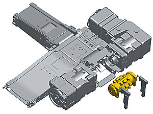
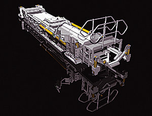
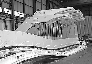
The Harvestline is a guyless interlocked grapple yarder with the ability to dis-engage the interlock for gravity logging. Built on either a log loader or excavator platform, the Harvestline is very stable and highly mobile for fast road changes and moving the yarder to the wood and not the wood to the yarder. Interlock or gravity logging with grapples and the stability to support a drum car, all without having a guyline makes the Harvestline is a very versatile harvesting system.
Features
- Dual drum interlocked hydraulic yarder, with haywire drum
- Ability to uphill or downhill log
- Interlock can be disengaged for skyline operations
- Active skyline mode with superior live skyline control for gravity logging
- No guylines for quick set-up and moves — very mobile
- 3,000 ft of 3/4” haulback and 1,700 ft 3/4” main line, 3,000 ft of haywire
- Excavator based so it can be taken off road if needed
- Industry leading control system for fast, smooth grapple yarding
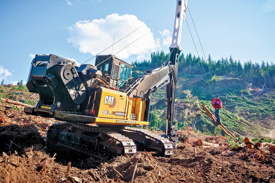
Exceptional Stability
With the new and improved Harvestline MK4, you can count on exceptional stability in a variety of conditions:
- When moving fully rigged
- Yarding off the side of the tracks
- When moving off-road
- At maximum payloads without a guyline
 WARNING